Alec Beckelman 1/4/2016
For this project we had to make a copy machine jam simulation. It needs to be able to detect when there is a jam, have the motor stop, the LED turn on and the buzzer turn on. then once the jam is fixed the motor can start to run again, the LED turns off and the buzzer will turn off (only upon reset, the LED will turn off right when the jam is no longer).

|
|
|
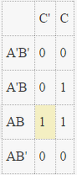
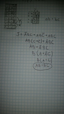
Wiring Diagrams
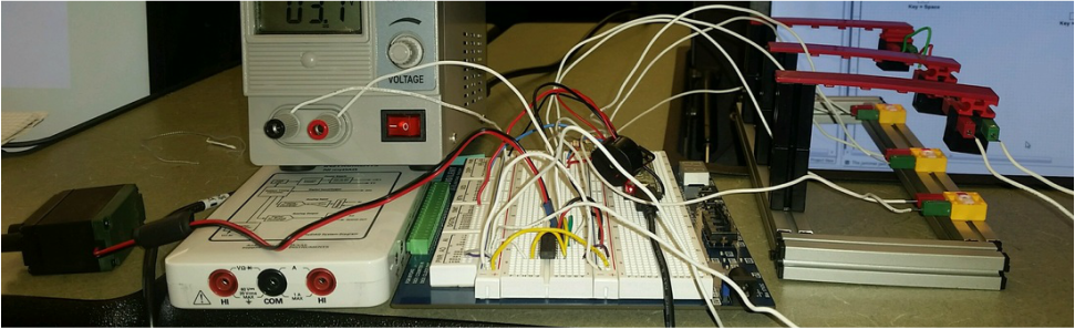
Part Functions
Resistors- limited the voltage going into the lights.
Combinational Logic Circuit- Used to detect a Jam. When the sensors AB or BC both detect paper (at the same time, one or the other) the motor is then stopped, the buzzer starts buzzing, and the LED lights up.
Flip Flop- The Flip Flop is used to have the buzzer stay on even if the jam is cleared. It will only silence once it has been separately cleared.
LED w/ Buzzer- When a Jam is first detected both the LED and Buzzer go on at the same time. However when it comes to them turning off that is a different story, the LED will turn off right when the Jam is gone, however the buzzer will stay on until the copier is reset.
Conclusion
This project had many similarities as other projects, wiring, using logic chips, using multi-sim to create and export to our chips. However this project also had some differences. 1. We used a "set" to create our copier jam project, using parts we haven't used before, so the concepts of what goes where, was a challenge. 2. We had to learn how to wire a motor, LED, and a buzzer to the board, simulating the copier, the Warning light and the buzzer that goes off during the jam. and 3. we had to create our multi-sim based around the new components (motor and buzzer) to have them stop and start when needed. and overall we took our knowledge from previous projects and stepped it up a little by adding the new components, and how to take not only our multi-sim to a breadboard, but then onto a "machine" as well.
