Project Overview
|
For this project we had to design and build a circuit to display our birth date on a seven segment display, our constraints consisted of using a common cathode seven segment display, 150-270 ohm resistors, K-Mapping technique to get the simplified expression, had to implement one NAND or NOR only logic circuit.
|
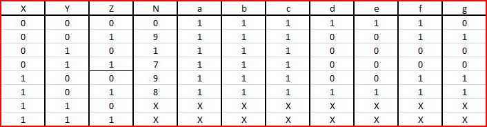
Truth Table
This truth table shows what inputs have to be entered to show a certain number. my N column shows the number that needs to be shown and everything to the right of the N are the the 7 segment display parts that would be on or off to create the number. The X's are the do not care values which means that it does not matter what they are because we don't need them.
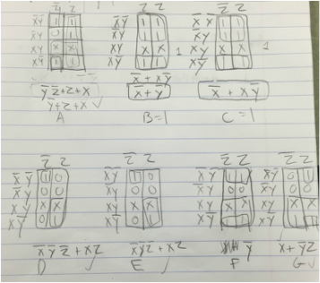
K-Mapping and Simplified Logic
|
K-Mapping works on the Idea of grouping, but first you have to set up the table, depending on how many variables you have you set up the table with each possible variable. then you take the values from the truth table and insert them into the K-map table. you then group all of the 1 values together to simplify, the bigger groups the better. My expressions are in sums of products form, I used this form because it's much easier to read and see what is actually going on within the circuit. K-Mapping is much simpler than Boolean algebra and less mistakes can be made. we needed an expression for each segment in the 7 segment display so we needed 7 expressions.
|
MultiSim implementation
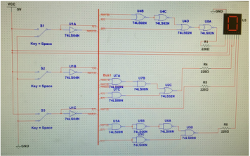
I chose to use a bus, a bus allows you to easily connect your components input to its output, and keeps everything very organized. There are 3 NOT gates, 4 NOR gates 3 AND gates, 1 OR gate, and 5 NAND gates. 6 total chips were needed to complete this 7 segment display circuit. We used NAND and NOR because they can in different arrangements, create any type of gate, so they are known as universal gates for that very reason. My NOR circuit used less gates than it would normally, however my NAND circuit used more, but in most cases you can use less chips then you would normally to create a circuit by using NAND and NOR. Common Cathode had to have the segments powered to display the segments, however if I used a Common Anode I would need to ground the segments to have them displayed.
Bill of Materials
|
Component:
1. Breadboard 2. NOT chip 3. NOR chip 4. AND chip 5. OR chip 6. NAND chip 7. Common Cathode 7-seg. display 8. Wires |
Quantity:
1. 1 2. 1 3. 1 4. 1 5. 1 6. 2 7. 1 8. about 45 |
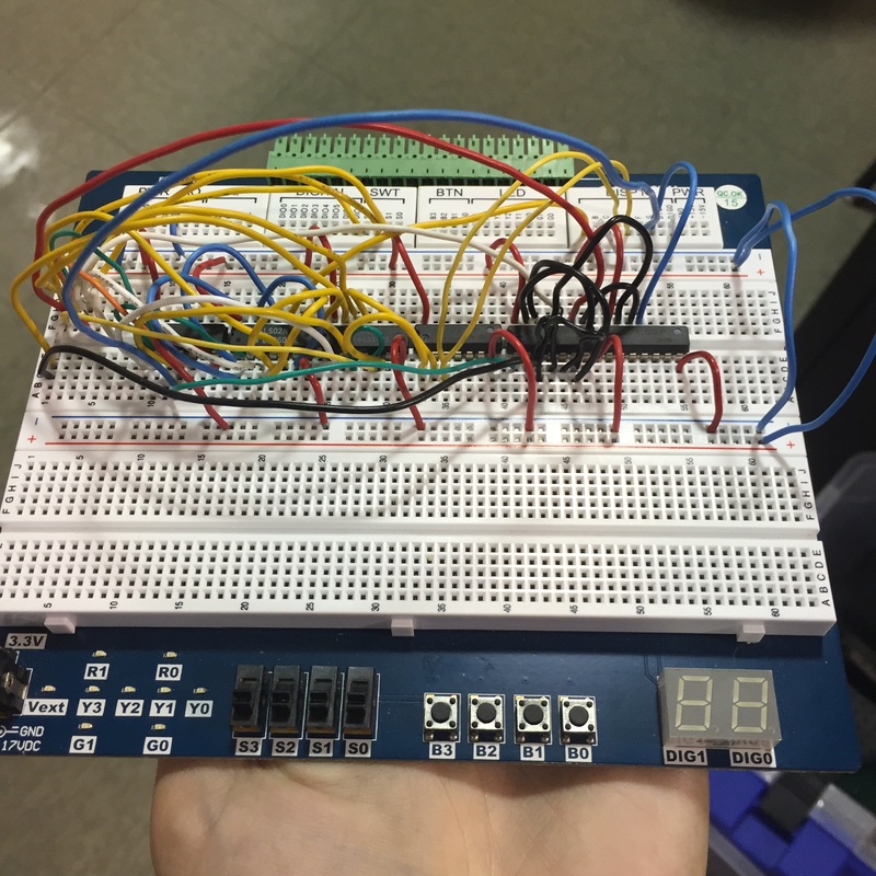
Bread Boarding
|
|
During bread-boarding I encountered many issues with the chips, once those were replaced my circuit had one segment left to fix (g), this was most likely due to a misplaced or missed wire somewhere on the board. Bread-boarding is difficult because there are so many minute details that can be easily overlooked, and if something accidentally comes undone or moved later on in the process it becomes more and more difficult to fix the problem.
Conclusion
This project showed me each step to get from the design of the circuit, to the final product. However there are a lot of different errors that can occur and this project showed that, from design mistakes, expression simplification and actual wiring of the breadboard, these challenges were overcome by having the original design, having this makes it very easy to fix mistakes in the later stages of the project. Next time I would definitely lay my circuit out more one by one, I tried to do this but the way I did it almost didn't make a difference, next time I would really want to break it down more and make sure every component is in working status before moving on.
