Project overview
|
For this project we needed to design a timer that counts 00 to 59. The design needs two control inputs and two output displays. Once the count reaches 60 the count needs to reset to 00. The two output displays are common cathode seven-segment displays that will require a multiplexed signal. The Ones unit display (0-9) is controlled by a synchronous counter designed with a 74LS163 MSI counter IC. The Tens unit display (0-6) is controlled by an asynchronus counter designed with SSI logic gates (J/K).
|
|
PLD Circuit
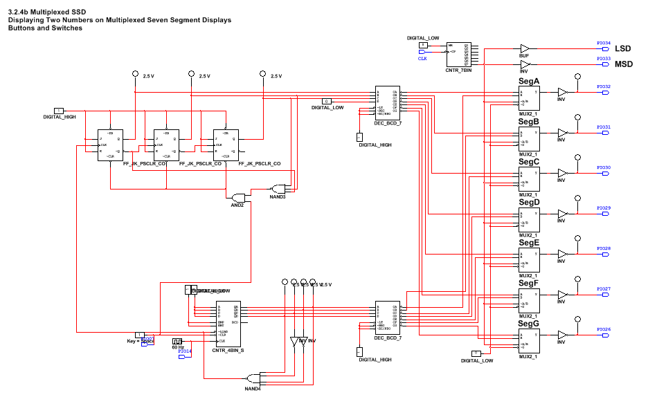
This project is very similar, the differences are the types of gates and the end number you are trying to get to, the general setup and multiplexed outputs are more or less the same. The main difference is the reset, it resets at 60 (shows 59) instead of 80.
Project Conclusions
1. The differences between synchronous and asynchronous circuits are that synchronous circuits are connected with the same external clock, and will not have a ripple. asynchronous circuits will have a ripple because the circuit is not connected to one external clock.
2. 74LS163 can only be an up counter, however it ends with the number detected whereas the 74LS193 can be up or down, and it detects the next number to stop.
3. To start off my circuit I started by creating the tens unit circuit, i placed the amount of J/K flip flops needed, and wired it completely. Then I connected the DEC_BCD_7 to the Q's of the flip flops. I then moved on to create the ones unit circuit. Which using a CNTR_4BIN_S, I connected the starting numbers by connecting A, B, C, D, to the Digital Low so it started at 0. Then I took the outputs from the Counter and I took two inverters to make the binary number to 1001 to make it reset at 9, I connected the wires to a Nand gate and connected it to the Load. Then I took the outputs from the Counter and connected them to the Decoder. To get the circuit to run I needed to connect a digital clock to the clock, and a switch to the clear. I placed an input pin (PIO14) onto the clock and an input pin onto the switch. I then connected the Load from the ones unit circuit to the clock of the tens unit circuit. so now once the ones unit circuit reaches 9 it will reset to 0 and drive the tens unit to count to 1. now to get the circuit to stop at 59 you need to create a reset. this is done by connecting a Nand gate from the output number you want on the tens place (6) to show a 5. so you connect to the right Q's and notQ's you need the binary number 110, then you connect that Nand gate to an And gate, which is also connected the the clear from the ones unit circuit, and set that to the clear of every flip flop, so then once the tens place reads a 6 it will reset cause the whole circuit to reset back to 00. Also this whole circuit is needed to be connected to a multiplexer, so i took the multiplexer from the DMV display project and just connected my circuit to it (you connect it by connecting to the Decoders which are connected to the multiplexers so you do not need to mess with them).
4. My classmates all had the general same design that I had on my board, maybe with a few changes in wiring or use of inverters instead of notQ's but other than that it was very similar to the rest.
